

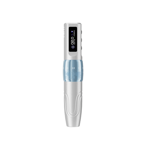


Choose the ATS wireless A4 printer with 20 compatible A4 thermal transfer sheets for routine lettering, compact designs and a station that prints from a phone, tablet or computer. Choose the ATTO A3 wireless thermal machine with 20 compatible A3 transfer sheets when a wider working-size outline can fit on one carrier with its placement marks. The useful reason to move up a format is keeping a critical line continuous or keeping multiple landmarks together on the same sheet.
A clear stencil depends on three things that can be tested independently. The file must hold the detail at its intended size. The printer and paper must reproduce that detail on the carrier. The artist must be able to place the proof without losing its position or continuity. This guide takes you through the first two stages and shows how to specify a station around the work it actually prints.
On this page
- Choose a printer from the work you print
- What DPI means on a thermal head
- Thermal darkness and media response
- Build a stencil layer that survives printing
- Bluetooth and USB production workflows
- A4 and A3 for sleeves, backs and shared studios
- Commission the station with measured proofs
- What to order and when to expand
- Purchasing and engineering FAQ
Choose a printer from the work you print
Define the usable footprint
Measure the artwork in the orientation you expect to print. Include the outermost essential lines, any registration marks and enough clear paper to handle the proof. This gives you a footprint for the actual carrier. An intricate name can fit comfortably on A4, while a simple shoulder arc may need A3 because the two ends and their placement references sit farther apart. Check both axes in the layout preview before comparing machines.
Decide what has to remain connected
A planned join can work when the edges of two modules meet in open space. A join through thin lettering or a long ornamental curve asks the artist to reproduce both angle and position at once. Identify the most important continuous feature before you choose the printer. If a wider sheet keeps it intact and eliminates a difficult join, the larger printer changes the work at the bench. If every composition naturally separates into small elements, A4 can remain the main station format.
Compare current ATTO routes on the same dimensions
| Decision | ATS wireless A4 | ATTO A3 wireless thermal machine |
|---|---|---|
| Format | A4-compatible thermal transfer sheets | A3-compatible thermal transfer sheets |
| Primary use | Routine lettering, small and medium outlines, compact station | Wider working-size compositions with connected features |
| Confirmed connection | Bluetooth from phone or tablet, USB from computer | Wireless workflow for a larger thermal layout |
| Initial consumables | A4, 20 sheets for working proofs | A3, 20 sheets, supplied without a box |
| Repeat supply | A4, 100 sheets for frequent printing | A3, 100 sheets for frequent large-format printing |
| Placement companion | 125 mL ATTO transfer gel, used according to its label | Same 125 mL option, selected separately |
| Evidence to seek on the first proof | Clear fine line and measured landmark span | All critical features and placement marks on one measured carrier |
What DPI means on a thermal head
Separate nominal dot pitch from the size of an image
Dots per inch describes the spacing of addressable positions at an inch scale. On a linear thermal head, a row of heating elements forms positions across the carrier. The transport advances the media to build the next rows. This gives the printer a cross-feed direction and a feed direction. Thin curves and diagonals exercise both. A catalogue DPI number alone cannot tell you how sharp a particular line will look through both axes after the printer, driver and paper have processed it.
For example, a hypothetical 203 dpi head has a nominal pitch of about 0.125 mm across an inch, since 25.4 mm divided by 203 is about 0.125 mm. A hypothetical 300 dpi head has a nominal pitch of about 0.085 mm. These are illustrations of dot geometry. The practical question is whether the lines and spaces in the artwork remain distinct on the proof. A nominal single-dot feature is a poor acceptance target because its visual width also depends on the input raster, image position and thermal response.
Keep pixels per inch in the source separate from printer DPI
A 100 mm feature occupies about 3.94 inches at working size. In a raster prepared at 300 pixels per inch, that feature spans roughly 1,181 pixels. Exporting it at the same physical width with more pixels gives the print pipeline more input samples, but the printer still maps the artwork onto its own grid. Increasing an already small raster by interpolation can create new pixel values around an edge while leaving the underlying contour vague. Start with a sharp source, or preserve the outline as vectors until it must be rasterized.
Read the edge in both directions
A diagonal line crosses the dot grid in steps. On a shallow curve, gaps between nearby details may narrow unevenly as the line turns. Test the actual angle and separation from the artwork. A vertical test line alone gives little information about a fine curved branch or paired contour. Put the same curve in two orientations while holding the physical size constant. If the fine feature survives in one orientation and disappears in the other, inspect the raster and the corresponding paper position before changing the entire layout.
| Quantity or observation | What it describes | How to check at the studio | What it helps you decide |
|---|---|---|---|
| Source pixel density | Samples available at intended artwork size | Check export dimensions against the physical span | Re-export from the original when the working image is coarse |
| Nominal DPI | Addressable output grid | Use verified manufacturer data for the exact printer | Compare hardware only after matching format and workflow |
| Fine line width | Visual width on the actual carrier | Compare a straight segment, a curve and a diagonal | Choose a clear stencil line at working size |
| Negative gap | Space between two printed marks | Check close parallel lines and narrow lettering counters | Decide whether to simplify or separate features |
| Printed scale | Physical size of the proof | Measure landmarks on the carrier in both axes | Correct layout or scaling before transferring |
Thermal darkness and media response
Understand the heat path
In a thermal stencil system, the head activates a sequence of positions as the carrier moves. The compatible media respond in those areas, creating the outline you inspect and later transfer. Electrical drive, pulse timing, feed behavior, contact and media response all influence the marks the artist sees. The engineering distinction is between the spacing of addressable positions and the intensity of the mark produced at a position. A finer grid can reproduce smaller positional steps. A change in darkness changes how the existing marks appear.
Compare separation before chasing darker output
When a route offers a darkness or density control, use the lowest tested setting that preserves a clear line and the adjacent gap under the station's normal viewing conditions. Test the same feature on the same media at two nearby settings if those settings exist. A faint line may become easier to follow, while a tiny space between nearby marks may close if both edges become visually heavier. Pick the proof with the clearest usable drawing, especially where two lines pass close to one another.
Hold paper and location steady
A pale mark on a single sheet can come from the paper or the way that sheet travelled through the printer. Repeat a short section on fresh compatible paper before changing several variables. If the same area repeatedly fades, place one copy of the test in the centre and another at the suspect position. Identical art lets you see whether the weakness follows the feature or remains fixed in the printer's working area. Inspect the carrier before transfer. A clean carrier followed by a weak placement calls for a transfer check.
| Proof pattern | What changes | What stays fixed | How to read it |
|---|---|---|---|
| Two darkness settings, when offered | One setting at a time | File, position, paper format and route | Keep the proof with clear lines and distinct gaps |
| Fresh sheet repeat | Sheet | Same compatible paper type, image and position | A clean repeat supports continuing with that format |
| Centre and edge | Position of identical test marks | Artwork, scale and paper | A recurring weak position gives support a useful sample |
| Thin and heavier companion | Width of one line | Same placement and paper | A surviving companion isolates a fine-detail problem |
| Paper and transferred outline | Stage | Same marks and working scale | A defect starting after printing belongs to placement |
Build a stencil layer that survives printing
Give each line a job
Start with the artist's full visual reference and create a separate stencil layer. Keep the external silhouette, deliberate overlaps, major boundaries and details you need to place accurately. For a portrait or shaded design, retain only the contour and interior references that genuinely guide placement. A dense representation of every shadow edge can obscure the eye, jaw or other anchor you need to find quickly. Compare the simplified stencil and complete art side by side so the reference remains available at the station.
Proof the smallest feature in context
A line may print well by itself and become hard to follow next to two others. Crop a short section from the actual art and print it at its final physical size, including adjacent marks. On lettering, include the counters and the shortest space between strokes. On an ornamental curve, include the place where the spacing tightens. On a portrait, include one feature where several boundaries meet. Examine the paper at working distance before moving closer. A usable guide should let you locate the feature as part of the drawing.
Control scale and orientation deliberately
Set the working dimensions in the file and check the page size in the route that sends it. Keep two measured landmarks on the first proof. For asymmetrical designs or lettering, confirm orientation through a short synthetic transfer when adopting a new workflow. One deliberate reversal in the approved file is easier to follow than an uncertain combination of a flipped image and a print setting. Use the same checked source for reprints so an adjustment to the size or mirror direction does not reappear between jobs.
Bluetooth and USB production workflows
Set the phone route up for one repeatable proof
Save the finished stencil layout where you can open the same version from the mobile device. Select the ATS from the supported Bluetooth workflow and confirm the working size and orientation before sending the first job. Print a short proof if the project has tight lettering or a new scale. Measure its two landmarks. Once you have the correct output, use the same file and page setup for another placement proof. Reopening a screenshot or an image preview can introduce an extra crop or size change between those two prints.
Use USB to compare the mobile output
The ATS gives the station a USB route from a computer as well as mobile Bluetooth. If a mobile print is cropped or scaled unexpectedly, compare the same checked layout through USB on the same compatible A4 paper. Treat the result as a comparison of file preparation and output routes. If USB preserves the span and the mobile proof differs, revisit the mobile page or import settings. If both reproduce the same unexpected result, inspect the source dimensions and margins first.
Give shared work a simple handoff
When two artists share a printer, distinguish the checked working layout from the reference artwork. The receiving artist needs to know the intended carrier format and where to measure the proof. Keep the transfer direction and registration marks visible in the prepared layout. When printing from a second device, start with the same file, compare the printed span and check orientation. A short common proof can eliminate the need to troubleshoot every job independently.
For example, one artist may prepare a run of small lettering proofs on A4 while another reviews a large back composition. Keep the smaller jobs together on their own prepared layout, each at its own working size. Reserve the wide format for the connected contour. That way the larger printer solves the width problem and the regular A4 station stays free for the routine queue.
A4 and A3 for sleeves, backs and shared studios
Build a sleeve around connected landmarks
Lay out the sleeve at working scale before deciding how many carriers it needs. Find the features that cross from one section to another, then separate them from independent motifs that can be positioned on their own. A long band, repeating ornament or running contour benefits from keeping the connected landmarks together. A sleeve made from individual motifs may fit several small A4 proofs naturally.
Compare a measured A3 layout for the critical connected section. Include two placement marks beyond the feature itself. Test one short synthetic placement near the likely join before printing the complete composition. If the connected section fits A3 but the full sleeve does not, move the remaining join to a simpler interval. Keeping the difficult line whole can be enough to make the larger format useful.
Place a back composition around its centre and wings
Use the centre axis and two outer landmarks to judge whether a back stencil benefits from A3. Print the landmarks and the main outline together if the checked area allows it. On the first proof, measure the centre-to-left and centre-to-right spans separately. A full-width measurement can hide a shift from the middle to one side. A layout that preserves both half-spans gives you a clearer placement reference.
For a composition extending past A3, keep the central anchor and one or more shared references in the proof plan. Plan matched modules at their original scale. Place joins in areas where you can see both sides against the centre. The wide printer is useful for holding larger connected sections. The proof layout still has to account for the full composition and the way the sections meet.
Choose a second printer around the work it removes from the queue
For a two-artist studio dominated by compact jobs, begin with one A4 setup and see which proofs actually compete for time. A second A4 station can make sense when both artists prepare small stencils independently and need the same paper route. Choose a mixed A4 and A3 station if the repeated conflict involves wide artwork that consumes several compact proofs or leaves a critical join. Separate the jobs by the carrier each needs.
| Work pattern | Proof to try first | Preferred station | Reason to expand |
|---|---|---|---|
| Lettering and compact motifs | One measured A4 layout | ATS A4 and compatible A4 media | Add capacity when routine proofs repeatedly overlap |
| Sleeve with connected ornament | One full-size section with both landmarks | A3 for the critical section, A4 for separate motifs | Preserve the line that would cross a difficult join |
| Wide back composition | A3 layout with centre and both outer marks | A3 for the complete proof or larger matched modules | Keep centre and wing relationships on the same carrier where possible |
| Two artists, mostly compact jobs | Short shared A4 proof from each device | One A4 station first, separate A4 route if both need it concurrently | Reduce conflicting repeat proofs on one device |
| Two artists, mixed compact and wide work | Measured A4 and A3 proofs from actual jobs | ATS A4 plus A3 wireless machine | Keep routine output moving while wide work stays at its intended scale |
Commission the station with measured proofs
Print a small test that resembles the work
Choose a short horizontal line, a vertical line and a curve. Add one tight pair of lines from the sort of artwork the station will produce. Put one measured span across the layout and another along it. The aim is to prove that the actual print route keeps the dimensions, shape and gaps you need. Include one matching mark off centre if you commonly use most of the sheet.
For lettering, put a short baseline and a small counter into the test. For a large composition, include a landmark near each usable outer edge. If the draft contains a very small detail that could disappear, print that detail at actual size alongside the spacing it will have in the design. That comparison is more useful than filling a sheet with generic resolution patterns.
Inspect scale, clarity and repeatability in that order
Start with a ruler on the carrier. Check whether the two spans match the design. Then inspect the curve and tight gap at normal viewing distance. Finish by making one repeat proof from the checked layout. Compare the same features at the same positions. When you add another device or a different compatible paper supply, a short repeat using that same proof makes the effect easier to identify.
If a landmark falls outside the usable area, move the layout or rotate it while preserving the intended dimensions. Check both axes after rotation. If the complete A3 artwork still extends past the usable space, plan the split before printing. If only a fine feature breaks, keep the geometry and compare a slightly clearer stencil line in a short proof. These adjustments address distinct problems and are easiest to judge separately.
Check a short placement before committing the full carrier
Once the carrier meets the size and clarity checks, place a short representative section on a compatible synthetic practice surface. Use the placement preparation suitable for that surface. Compare the same landmarks and fine marks against the paper proof. The test can reveal a shifted corner or an awkward contact point without consuming a full sheet. On a long carrier, choose a test that contains the curve or direction change most likely to move during placement.
For a recurring print defect, return to the controlled repeat proof and identify whether it starts in the source, on the carrier or during transfer.
Compare feed geometry without changing the artwork
A sheet can move diagonally through the printer while the file remains correctly sized. To separate angle from size, print a rectangle with two measured sides and compare its opposite edges to the corresponding carrier edges. A rectangle whose dimensions match but whose top line is angled against the carrier suggests a different problem from a rectangle that stays square on the sheet but measures smaller in both directions. Inspect the saved preview to establish which angle is present in the file. Feed another compatible sheet squarely according to the printer instructions and compare the same points. This lets you decide whether to inspect the page layout, how the sheet was loaded or a recurring problem to show the printer supplier.
Consider the same distinction when only one mirrored half seems different. Measure the corresponding landmarks on the flat proof before comparing visual symmetry on a curved practice form. If the dimensions are correct on paper but appear different after placement, compare the same halves on a flat synthetic surface. A large carrier can preserve the geometry through printing while the surface or the direction of the placement changes how the outline reads.
Recognize what a clean proof can save
Suppose a studio produces a long ornamental outline with two overlaps on three compact carriers. Each overlap needs alignment at two landmarks. A continuous wider carrier removes both joins if the outline fits. If only the two pieces around the most demanding curve fit together, the wider format can still remove one join and leave the final section on a small carrier. Evaluate the result on the carrier and at placement. Count the joins that remain and compare the time you spend adjusting them on a real proof before you equip a second station.
The same reasoning works the other way. If a large share of the studio's work consists of independent names or symbols, arrange those jobs on checked compact layouts. A shared A4 proof can hold several outlines at their different intended sizes, provided each one has room around it and retains its dimensions. Separating wide and compact work in this way makes the purchasing decision depend on the drawings and the bench workflow.
What to order and when to expand
Start with the complete regular station
Order the ATS wireless A4 printer, the A4 thermal transfer paper 20-pack and the ATTO transfer gel, 125 mL for regular printing and placement. Follow the gel label and applicable preparation process. Order 100 A4 sheets when you already use that compatible format for frequent proofing. The larger pack is a refill decision, while the printer format is a design decision.
Move up when a full-scale A3 proof solves the layout
Choose the A3 wireless thermal machine and 20 A3 transfer sheets if a larger carrier keeps your required outline and marks together. Try 10 A3 sheets for a short evaluation or use 100 A3 sheets for recurring large-format preparation. The 10- and 20-sheet choices are supplied without a box. Keep the smaller printer for jobs where you can work at full size without a difficult join.
Scale the purchase to the actual bottleneck
If a station produces clean A4 proofs and needs only a steady supply, replenish compatible sheets. If a large outline loses a critical connection at a join, test A3. If a printer repeatedly loses detail in the same paper position after a fresh compatible sheet and checked file, show the relevant proofs to support. If the paper proof is sharp and the defect starts only during placement, put the next trial into the surface, alignment and handling. Each purchase should make the next working proof easier to produce or place.
| Purchase decision | Start here | Change when |
|---|---|---|
| First compact station | ATS A4, 20 A4 sheets, 125 mL transfer gel | Move to A3 for the wider connected outline |
| Initial large-format trial | A3 printer and 10 compatible A3 sheets | Move to 20 for regular preparation or 100 for repeated wide work |
| Established compact workflow | Compatible 100 A4 sheets | Add a station when concurrent proofing is a consistent constraint |
| Mobile placement kit | Compatible paper and 30 mL transfer gel | Choose 125 mL for the regular station |
| Frequent placement | Compatible thermal paper and 250 mL transfer gel | Match the pack and bottle to actual studio consumption |
Purchasing and engineering FAQ
Does higher DPI always give a more useful stencil?
A finer addressable grid can represent smaller position steps. Compare the lines and negative gaps you need on a measured proof with the same media and physical dimensions. Choose the equipment that reproduces those features in the actual workflow. Keep line separation, usable page area and ease of repeat printing in the decision.
Is darkness the same as thermal resolution?
DPI describes position spacing, while darkness describes the visible response at those positions. When a control is available, compare two settings with the same layout and compatible sheet. Keep the setting that preserves both the contour and the narrow spaces around it.
How do I prepare a raster for a fine outline?
Start from a sharp source at the intended dimensions and remove background textures that interfere with the outline. Preserve vectors until the final export if the artwork is available that way. Proof the smallest relevant feature beside its neighbors to check that they stay separate.
Can Bluetooth change the scale of a design?
The mobile file and print settings determine how the artwork is laid out for the job. Compare the same checked file through the ATS Bluetooth and USB routes. Measure the same landmark span on both carriers so any size difference is easy to identify.
Is A3 the first choice for every sleeve?
Use A3 when a long connected line and its landmarks fit together on the wider proof. Use A4 for discrete elements that fit comfortably at working size. A sleeve can use both routes when one connected section needs the extra space and other motifs stand alone.
What is the first proof for a broad back design?
Print the centre axis and two outer landmarks in a layout that preserves the intended dimensions. Measure the centre-to-side distances separately. If the complete shape exceeds the checked A3 area, build sections from the same working source and keep shared alignment points visible.
Which consumable should I buy if I see a faint area?
Try a fresh compatible sheet before ordering a larger pack or replacing hardware. If the weakness follows the drawing, inspect the file. If it stays in the same print position on fresh compatible sheets, bring matching reference proofs to support. If it begins after transfer, check placement first.
Can I arrange multiple small stencils on one A4 sheet?
Yes. Put them on one checked layout at the physical sizes you intend to print. Leave room to handle each proof individually and check one working span on each shape. The shared layout is especially useful for repeat printing of several compact designs.
What should a two-artist studio buy first?
Start with the complete A4 station if both artists mostly print compact outlines. Add another A4 route when concurrent routine proofs consistently compete for one device. Add A3 when the second route needs to carry a genuinely wider working outline or preserve a critical connection.